Setting up a simulation
Create a new project
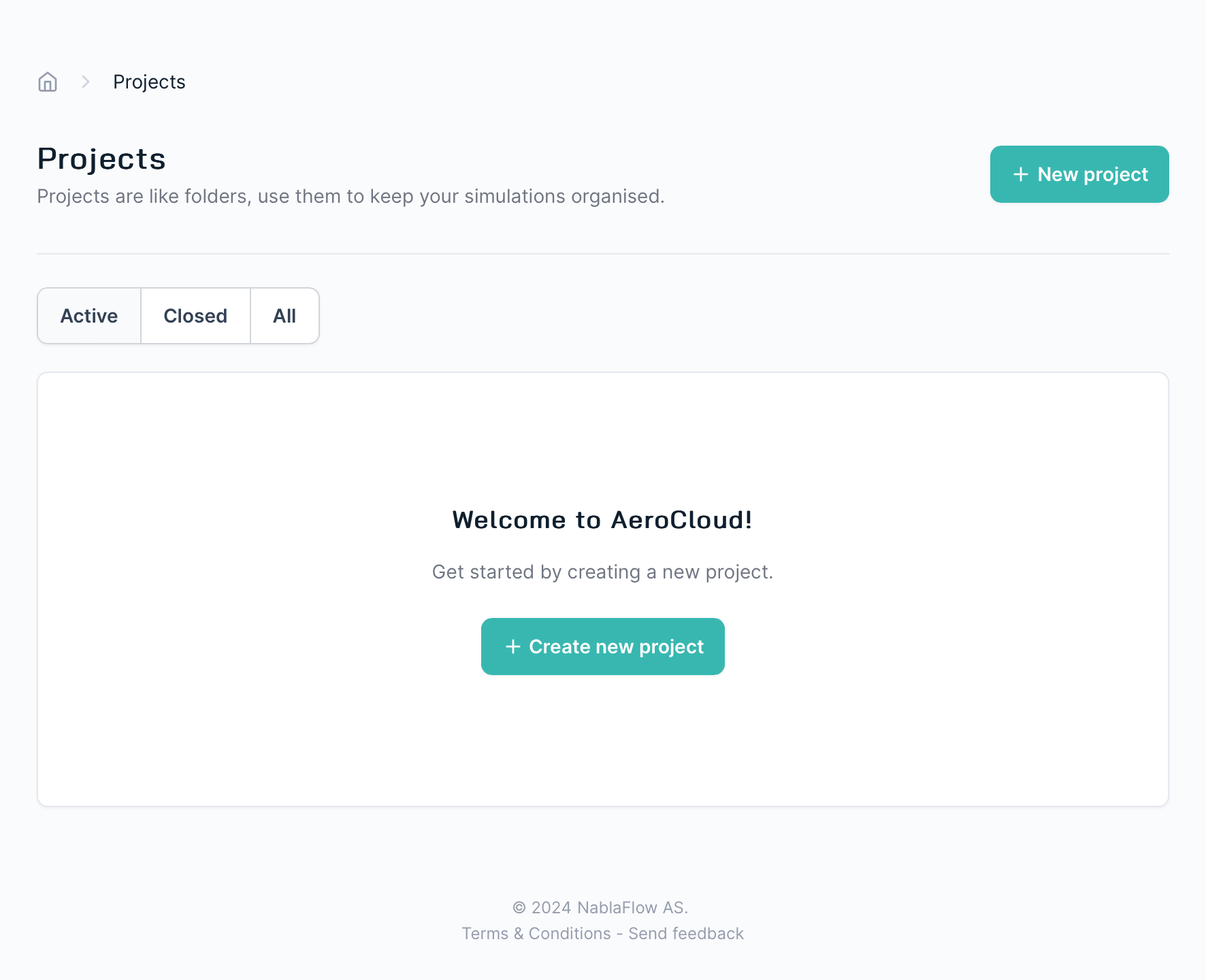
After signing in to your AeroCloud account, you’ll be presented with your project list.
Before you can create a new simulation you must create (or select) a project for it.
A project is just a way to collect & manage related simulations.
For example, you might choose to create a project to hold all of the simulations in a new case study, or to collect all of the simulations associated with a certain product development programme.
Click the button to create a new project (or select an existing one) & continue.
Create a new simulation
Click the button to start creating a new simulation.
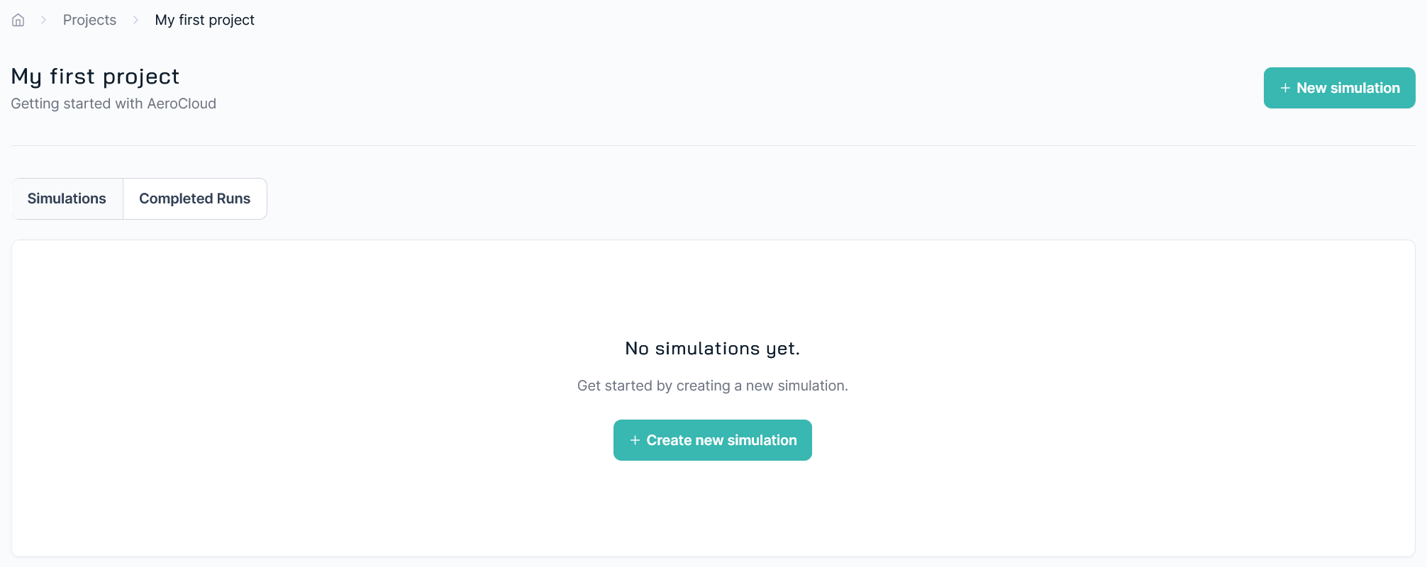
If your project has existing simulations then you’ll see them here.
Configure your simulation
First you’ll need to select the quality level for your simulation.
Essentially the higher the quality level, the higher the resolution & the more detail your simulation will capture.
Accordingly, the higher the quality level, the longer the simulation will take & the more it will cost.
Find out more details about the quality levels here.
Next, you need to fill out the simulation settings:
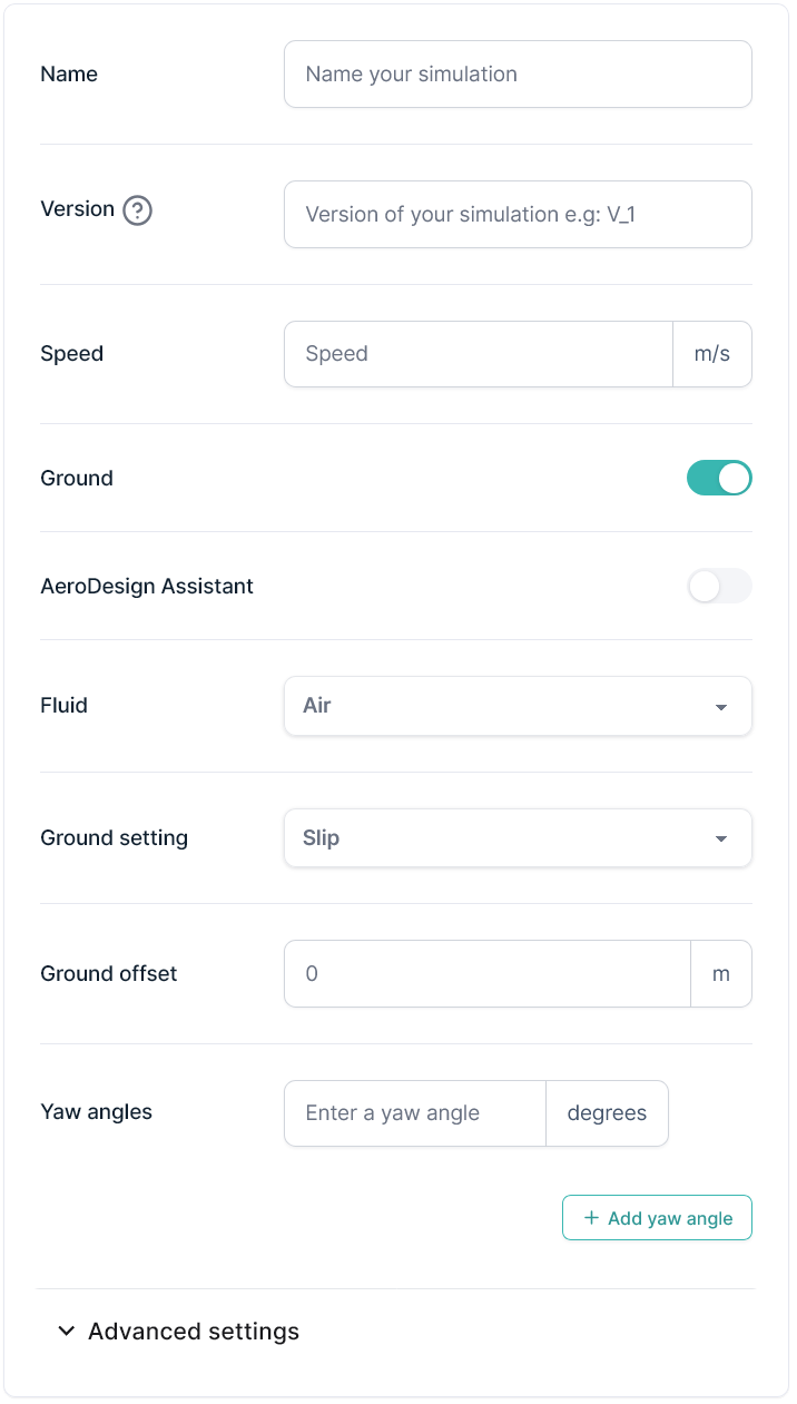
- Give your simulation a name - this will be your simulation’s main identifier in the results pages, reports etc so it’s worth being compact, but descriptive.
- You also have the option to tag your simulation with a version - this can be useful to differentiate it from others with a similar description/setup.
- Set the fluid speed in metres per second
- Google Convert is one quick way to convert between speed units.
- Select whether to include a ground (e.g. for a car) or ceiling (e.g. for the submerged part of a boat hull) boundary in the simulation - by default, the model is placed in the centre of the domain with neither active (e.g. for an airplane in free flight).
- When enabled, the boundary condition can be set to slip or moving. A moving condition applies the inlet fluid velocity vector to the boundary plane, e.g. simulating a vehicle moving relative to a static ground or a boat moving relative to static water.ℹ️Note: This setup corresponds to experimental testing conditions where the fluid direction at the boundary is fully aligned with a rolling belt floor or with the moving water, and where both share the same velocity magnitude.
- If you’ve chosen to include a ground plane it will (by default) be positioned to match the lowest point in your input geometry. You can change this behaviour by specifying a ground offset.
- A positive value will move the ground plane away from your model - useful for creating a gap between your model & the ground.
- A negative value will move the ground plane towards your model - useful for creating a small intersection between tyres & ground.
- If you’ve chosen to include a ceiling plane it will (by default) be positioned to match the highest point in your input geometry. You can change this behavior by specifying a ceiling offset.
- A positive value will move the ceiling plane away from your model - useful for creating a gap between your model & the ceiling.
- A negative value will move the ceiling plane towards your model - useful for creating a intersection between your geometry and the ceiling (e.g. to simulate a boat’s underwater hull)
- Toggle whether the Aero design assistant should be activatied. If active, an additional adjoint simulation will be run, producing a drag sensitivity map. This provides guidelines for how the design can be improved with an objective to reduce drag force. This feature will add an additional cost to the simulation.
- Select the simulation fluid – air or water;
- Select your desired yaw angle (i.e. the relative angle of the incoming fluid to your input geometry).
- You have the option to specify several yaw angles in this section, this is to speed up the creation of yaw angle sweeps & to allow the results to be grouped together in the results page.
- Note: each yaw angle is charged separately.
Upload your model
Upload the geometry for your simulation using the model preview window.
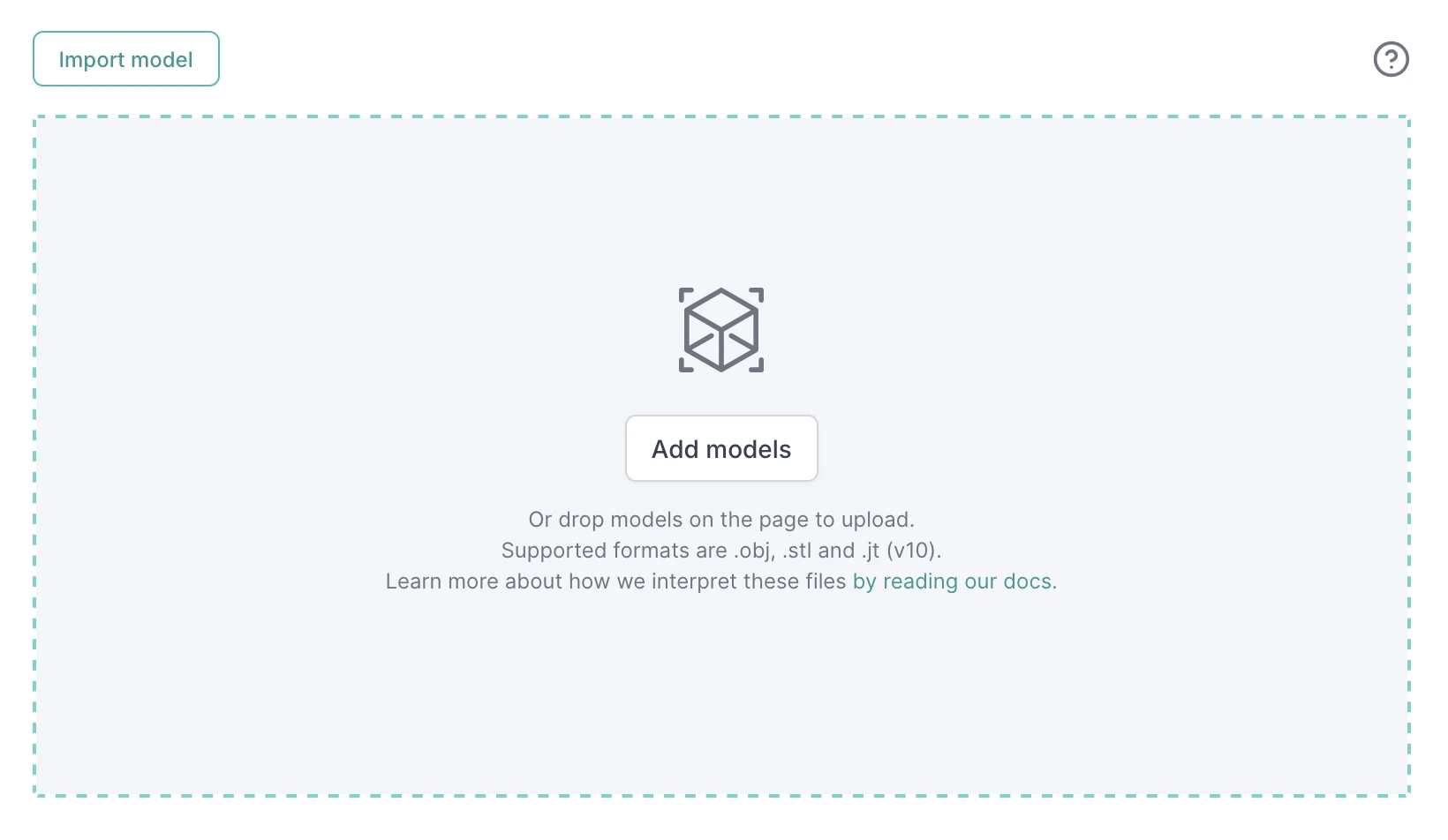
AeroCloud accepts geometries in the following standard formats: STL, Wavefront OBJ or JT v10 (beta) .
- STL: each file is treated as a single part, because no information about parts subdivison is present.
- OBJ: each group (
g ...) is treated as a separate part. Any line that is not vertices or faces is ignored. - JT v10 (beta): each node of type “Tri Strip” is considered a part and named uniquely according to the parent “Part” node. Only “Tri Strip” meshes from LOD #0 are decoded, ensuring the maximum resolution possible is used.⚠️Only self-contained JTs are guaranteed to be supported. JTs that are split into assembly and parts MIGHT work only if all part files contain enough information to reconstruct the original scene.
Any named parts found in your file will be listed below the model preview window and are maintained throughout the simulation for easy reference.
AeroCloud does not change the co-ordinate system of your models, meaning you can easily upload multiple files to create an assembly of parts, as long as they were all exported with a common datum.
If you have models stored in your model catalog, you can use the “Import model” button to add them to your simulation.
Configure the orientation and dimensions of your model
AeroCloud uses a right-handed coordinate system with Z-axis up and X-axis backwards.
If your model is defined differently (different modelling software use different conventions) then you can use the rotation buttons to re-orient your model.
STL and OBJ-files do not contain information about the model scale. Therefore you must set the units for each model accordingly.
Orientation & scale changes are shown live in the preview window, making them very easy to check (& adjust) before going any further.
Repeat this process adding, orienting & scaling all of the geometry files you wish to simulate.
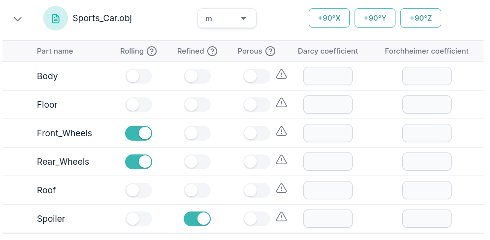
Rolling Parts
Rolling parts (wheels, brake discs etc.) can be setup via the model preview window.
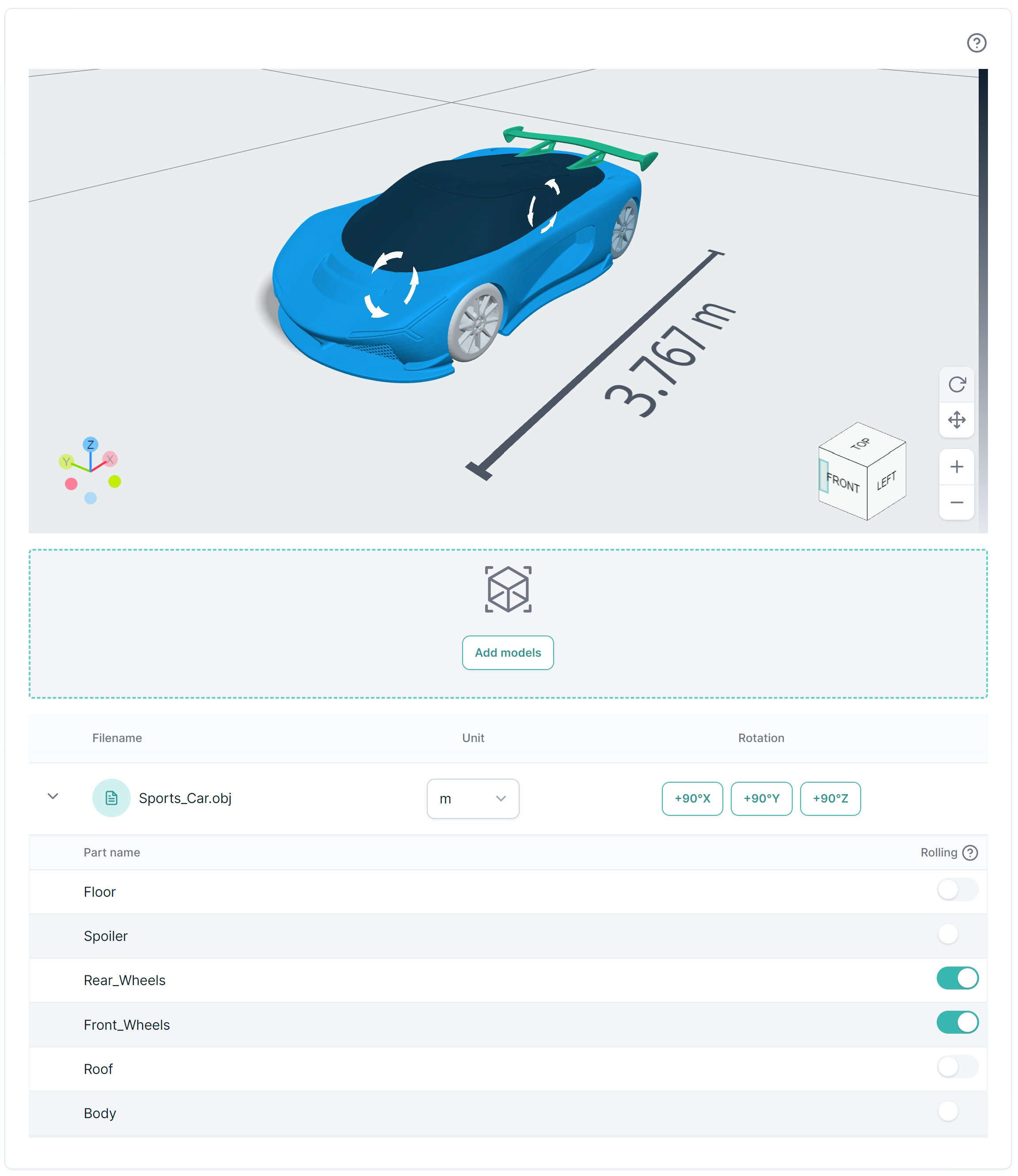
Expand the parts list for your input file & toggle the “Rolling” option for any part that you’d like to be rolling (they’ll have spinning indicators added to them in the preview window).
The angular velocity & rotation axis are automatically set for each rolling part.
- The angular velocity is based on the radius of the object & the model-aligned fluid speed.
- The rotation axis is parallel to the ground (i.e. Y-normal) with its origin at the geometrical centre of the rolling part.
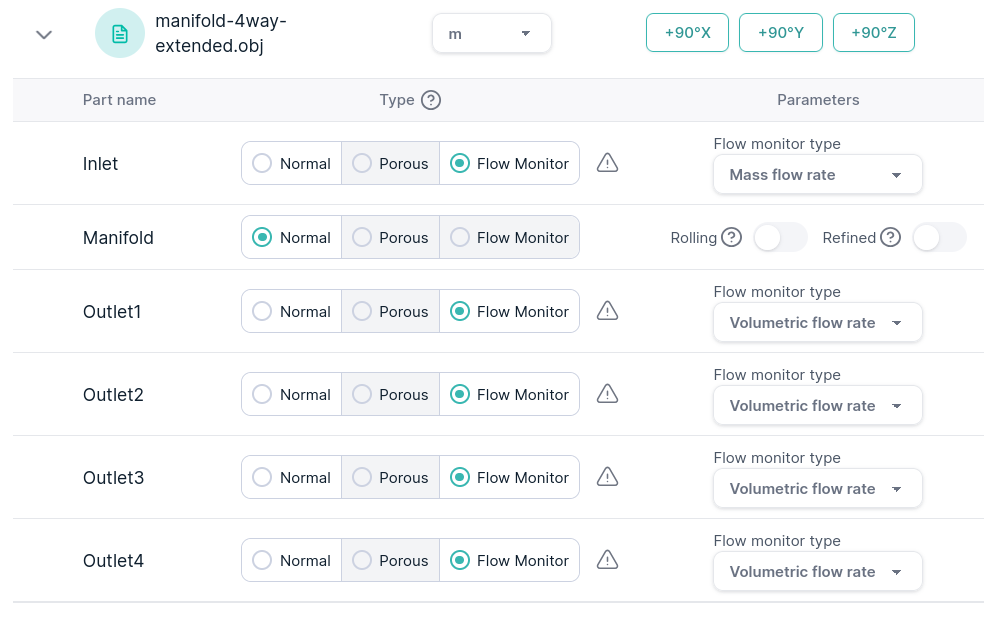
Flow monitors
You can monitor the flow fields on specific surfaces, together with the mass or volumetric flow rate passing through them.
Upload a reference surface where you want to inspect these quantities and flag it as a flow monitor, then use the drop-down menu to choose whether to evaluate the mass or volumetric flow rate.
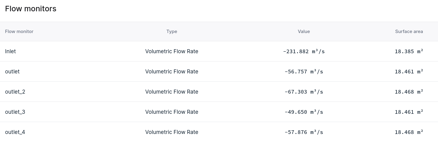
You will then be able to visualize velocity, static pressure, and total pressure in the 3D view, while the mass/volumetric flow rate values are reported in a table.
Refined parts
You can increase the mesh refinement on individual components to achieve a more accurate geometric representation in regions that are critical for reproducing detailed flow behaviour.
This setting does not increase the total number of cells used in the mesh, but rather redistributes them, making the mesh finer around the selected part.
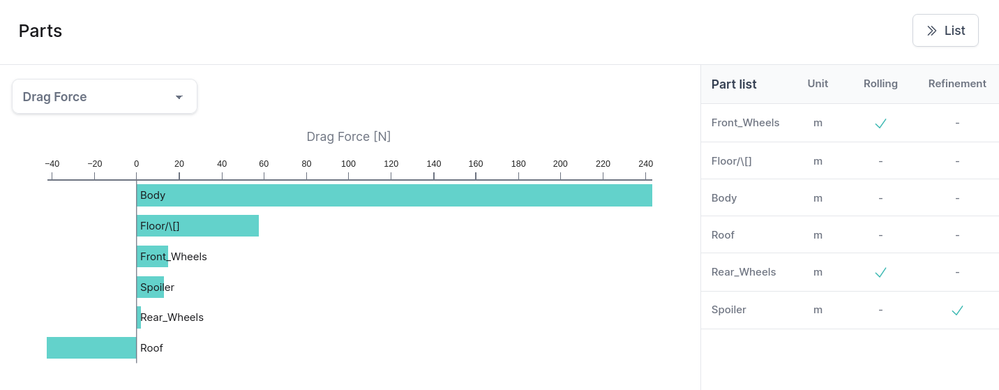
It is possible to check the refinement status for each part after the simulation has been completed, in the table of parts at the bottom of the results page.
How to use it:
- Subdivide the geometry into multiple parts representing regions of different complexity or interest.
- Add refinement to parts where you want to focus on details of the geometry or flow field, e.g. car spoiler, mirrors, air deflectors etc.
- Limit the total surface area of refined parts to include only regions of special interest, to avoid excessive decimation on the remaining mesh.
- If the model has two thin adjacent geometries, apply refinement to both of them since the surrounding region will be at same refinement level by default.
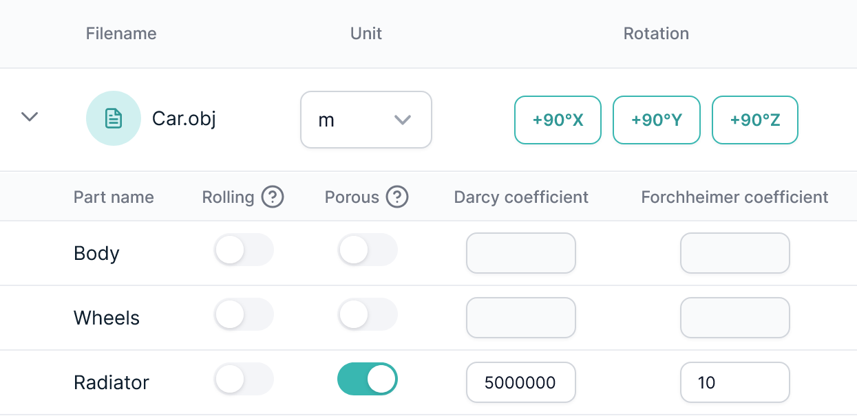
Porous media
Porous media can be added to the simulation to model pressure drop through e.g. heat exhangers, vegetation or other porous materials.
Expand the parts list for your input file & toggle the “Porous media” option for any part.
Next you will be promted to enter the porous pressure drop coefficents for the Darcy-Forschheimer equation. These can be derived from experiments for the porous media in question or estimated from models for spesific types of porosity.
- The porosity will be defined as isotropic, meaning that the pressure drop per length unit will be equal in all directions.
- The porous zones will contribute to the total forces acting on the model.
Review your simulation request & submit
You’ll now be asked to check that your simulation settings are as intended.
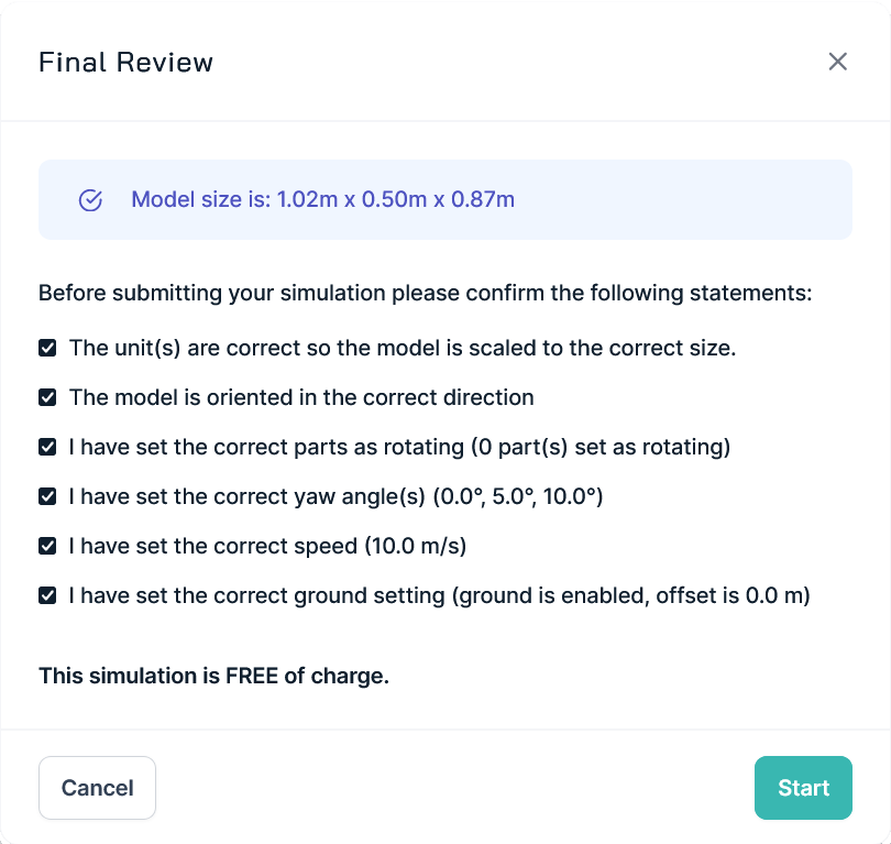
Pay extra attention to the model size & orientation - if either of those are wrong, you can easily change them in the model preview panel.
If your model doesn’t have closed surfaces, please pay attention: the flow will enter cavities inside it. In some cases this is expected, for example when you want to evaluate the flow inside a car. In other cases this will lead to a suboptimal cell usage compared to a watertight model and to imperfections on surfaces.
Tick off the boxes as you make your checks.
Click start if everything is correct.
Your simulation will then be started and you’ll be notified, by email, once the results are available.